Twisted pair cabling is a type of wiring in which two conductors of a single circuit are twisted together for the purposes of improving electromagnetic compatibility. Compared to a single conductor or an untwisted balanced pair, a twisted pair reduces electromagnetic radiation from the pair and crosstalk between neighboring pairs and improves rejection of external electromagnetic interference. It was invented by Alexander Graham Bell.[1]
Explanation
History
Unshielded twisted pair
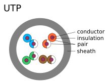
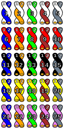
Unshielded twisted pair (UTP) cables are found in many Ethernet networks and telephone systems. For indoor telephone applications, UTP is often grouped into sets of 25 pairs according to a standard 25-pair color code originally developed by AT&T Corporation. A typical subset of these colors (white/blue, blue/white, white/orange, orange/white) shows up in most UTP cables. The cables are typically made with copper wires measured at 22 or 24 American Wire Gauge (AWG),[5] with the colored insulation typically made from an insulator such as polyethylene or FEP and the total package covered in a polyethylene jacket.
For urban outdoor telephone cables containing hundreds or thousands of pairs, the cable is divided into small but identical bundles. Each bundle consists of twisted pairs that have different twist rates, as pairs having the same twist rate within the cable can still experience some degree of crosstalk. The bundles are in turn twisted together to make up the cable.

UTP is also the most common cable used in computer networking. Modern Ethernet, the most common data networking standard, can use UTP cables, with increasing data rates requiring higher specification variants of the UTP cable. Twisted-pair cabling is often used in data networks for short and medium-length connections because of its relatively lower costs compared to optical fiber and coaxial cable.
As UTP cable bandwidth has improved to match the baseband of television signals, UTP is now used in some video applications, primarily in security cameras.[6] As UTP is a balanced transmission line, a balun is needed to connect to unbalanced equipment, for example any using BNC connectors and designed for coaxial cable.
Cable shielding
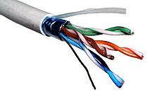

Twisted pair cables may incorporate shielding in an attempt to prevent electromagnetic interference. Shielding provides an electrically conductive barrier to attenuate electromagnetic waves external to the shield. The shield also provides a conduction path by which induced currents can be circulated and returned to the source via ground reference connection. Such shielding can be applied to individual pairs or to a collection of pairs. Shielding may be foil or braided wire.
When shielding is applied to a collection of pairs, it is usually referred to as screening, but usage among vendors and authors in applying such words as screening, shielding, and STP (shielded twisted pair) can be subject to variability.[7][8] ISO/IEC 11801:2002 (Annex E) attempts to internationally standardize the various designations for shielded cables by using combinations of three letters - U for unshielded, S for braided shielding (in outer layer only), and F for foil shielding - to explicitly indicate the type of screen for overall cable protection and for protecting individual pairs or quads, using a two-part abbreviation in the form of x/xTP.
Shielded Cat 5e, Cat 6/6A, and Cat 8/8.1 cables typically have F/UTP construction, while shielded Cat 7/7A and Cat 8.2 cables use S/FTP construction.[9]
Because the shielding is conductive, it may also serve as a path to ground. A foil-shielded, twisted pair cable may have an integrally incorporated grounding wire called a drain wire which makes electrical contact with the shield. The purpose of the drain wire is for easy connection to terminals which are usually designed for connection of round wires.
Common shield construction types include:
- Individual shield (U/FTP)
- Individual shielding with aluminum foil for each twisted pair or quad. Common names: pair in metal foil, shielded twisted pair, screened twisted pair. This type of shielding helps prevent EMI from entering or exiting individual pairs and also protects neighboring pairs from crosstalk.
- Overall shield (F/UTP, S/UTP, and SF/UTP)
- Overall foil, braided shield or braiding with foil across all of the pairs within the 100 ohm twisted pair cable. Common names: foiled twisted pair, shielded twisted pair, screened twisted pair. This type of shielding helps prevent EMI from entering or exiting the cable.
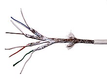
- Individual and overall shield (F/FTP, S/FTP, and SF/FTP)
- Individual shielding using foil between the twisted pair sets, and also an outer foil or braided shielding. Common names: fully shielded twisted pair, screened foiled twisted pair, shielded foiled twisted pair, screened shielded twisted pair, shielded screened twisted pair. This type of shielding helps prevent EMI from entering or exiting the cable and also protects neighboring pairs from crosstalk.
An early example of shielded twisted-pair was IBM STP-A, which is a two-pair 150 ohm S/FTP cable defined in 1985 by the IBM Cabling System specifications, and used with Token Ring or FDDI networks.[7][10]
- ^ The code before the slash designates the shielding for the cable itself, while the code after the slash determines the shielding for the individual pairs:
- U – unshielded
- F – foil shielding
- S – braided shielding (outer layer only)
- TP – twisted pair
- TQ – twisted pair, individual shielding in quads
Types
Analog telephone
Before digital communication and Ethernet became widespread there was no international standard for telephone cable. Standards were set at a national level. For instance, in the UK the General Post Office specified CW1293 and CW1308 cables. CW1308 was a similar specification to the earlier CW1293 but with an improved color code. CW1293 used mostly solid colors on the cores making it difficult to identify the pair it was twisted with without stripping back a large amount of sheath. To solve this problem. CW1308 has narrow rings of the paired color printed over the base color. Both cables are a similar standard to category 3 cable.[11][12]
Prior to the common use of polyethylene and other plastics for insulation, telephone twisted pair cable was insulated with waxed paper or cotton with a wax coating applied to the copper. The overall sheath of this type of cable was usually lead. This style of cable came into use in the late 19th century shortly after the invention of the telephone.[13] The cable termination in termination boxes were sealed with molten wax or a resin to prevent the ingress of moisture which would seriously degrade the insulating properties of the paper insulation.[14] However, such seals made future maintenance and changes more difficult. These cables are no longer made but are still occasionally encountered in old buildings and in various external areas, commonly rural villages.
Building infrastructure
Loaded
A loaded twisted pair has intentionally added inductance and was formerly common practice on telecommunication lines. The added inductors are known as load coils and reduce attenuation for voiceband frequencies but increase it on higher frequencies. Load coils reduce distortion in voiceband on very long lines.[19] In this context a line without load coils is referred to as an unloaded line.
Bonded
A bonded twisted pair is a construction variant in which the two wires of each pair are bonded together for the length of the cable. Pioneered by Belden, it is intended to help assure configuration consistency during and after installation. One key benefit is that the noise immunity performance of the cable can be protected despite potentially rough handling.[20] The enhanced performance may be unnecessary and bonding reduces the flexibility of the cable and makes it prone to failure where it is flexed.[21]
Twisted ribbon cable

A twisted ribbon cable is a variant of standard ribbon cable in which adjacent pairs of conductors are bonded and twisted together. The twisted pairs are then lightly bonded to each other in a ribbon format. Periodically along the ribbon, there are short sections with no twisting where connectors may be attached using the usual ribbon cable IDC techniques.[22]
Solid-core vs. stranded cable
A solid-core cable uses one solid wire per conductor and in a four pair cable there would be a total of eight solid wires.[16] Stranded conductor uses multiple wires wrapped around each other in each conductor and in a four pair with seven strands per conductor cable, there would be a total of 56 wires (2 per pair × 4 pairs × 7 strands).[16]
Solid core cable is intended for permanently installed runs (permanent link). It is less flexible than stranded cable and is more prone to failure if repeatedly flexed due to work hardening. Stranded cable is used for fly leads at patch panel and for connections from wall-ports to end devices (patch cord or drop cable), as it resists cracking of the conductors.
Connectors are designed differently for solid core than for stranded. Use of a connector with the wrong cable type can lead to unreliable cabling. Plugs designed for solid and stranded core are readily available, and some vendors even offer plugs designed for use with both types. The punch-down blocks on patch-panel and wall-port jacks are designed for use with solid core cable. These work via the insulation-displacement method, whereby the device pierces the sides of the insulation and "bites" into the copper conductor to form a connection.
Advantages
- Electrical noise going into or coming from the cable can be prevented.[23]
- Crosstalk is minimized.[23]
- Cheapest form of cable available for networking purposes.[23]
- Easy to handle and install.[23]
Disadvantages
- Deformation: twisted pair's susceptibility to electromagnetic interference greatly depends on the pair twisting schemes (sometimes patented by the manufacturers) staying intact during the installation. As a result, twisted pair cables usually have stringent requirements for maximum pulling tension as well as minimum bend radius. This fragility of twisted pair cables makes the installation practices an important part of ensuring the cable's performance.[24]
- Delay skew: different pairs within the cable have different delays, due to different twist rates used to minimize crosstalk between the pairs. This can degrade image quality when multiple pairs are used to carry components of a video signal. Low skew cable is available to mitigate this problem.[25][26]
- Imbalance: differences between the two wires in a pair can cause coupling between the common mode and the differential mode. Differential to common mode conversion produces common mode currents that can cause external interference and can produce common mode signals in other pairs. Common mode to differential mode conversion can produce differential mode signals from common mode interference from other pairs or external sources. Imbalance can be caused by asymmetry between the two conductors of the pair from each other and in relationship to other wires and the shield. Some sources of asymmetry are differences in conductor diameter and insulation thickness. In telephone jargon, the common mode is called longitudinal and the differential mode is called metallic.
| This article uses material from the Wikipedia article Metasyntactic variable, which is released under the Creative Commons Attribution-ShareAlike 3.0 Unported License. |